

Introduction: Combined Dividing Head and Rotary Table Step Indexer.


This step indexer combines the functions of both the dividing head, with its axis of rotation in the horizontal plane, and the rotary table with its axis of rotation in the vertical plane.
Using an Arduino Uno to control a stepper motor, it can precisely divide a circle into equal parts, very handy for drilling equally spaced holes in a tube, cutting gears or machining custom control knobs.
Supplies

Inspiration for this project came from watching Myfordboy's Youtube series on using a stepper to drive a 5C spindexer.
The electronics and Arduino sketch were designed by Gary Liming. His blog on the subject is well worth a read.
I wired mine according to his provided diagram, but omitted the temp sensors.
- Arduino Uno.
- Arduino 6 button 16x2 keypad shield.
- TB6600 stepper driver.
- Mmintbox 1 Enclosure by Vector_Mayhem from Thingiverse for housing the electronics.
- 250W ATX power supply from an old pc.
- Moons Nema 23 stepper (23HS2072) 8mm shaft, recovered from a Xerox WorkCentre.
- Industrial worm gearbox found at the scrapyard.
- High carbon 25mm dia x 90mm long shaft for the gearbox output, given free from Zaya Metal Trading in Cape Town.
- !00mm ODx25mm ID x 10mm plate for the output shaft.
- 2 x 100mm equal angle plate, 120mm wide and 15mm thick, diy cast from a Mitsubishi Pajero 3.8 V6 cylinder head, also from the scrapyard.
- 5mm flat bar for the stepper motor brackets.
- various M6 and M10 bolts/screws for assembly.
Attachments

Step 1: The Electronics


Because I'm using a large ratio 100:1 gearbox, I set the stepper driver micro stepping off, ie micro steps = 1 in the sketch before compile and upload to the Uno.
I used polyurethane to make the buttons, but it sets quickly leaving a lot of air bubbles. A better choice would have been the clear Oogoo (Sugru substitute) as suggested by the author of the enclosure.
Step 2: The Angle Plates


My first casting was a flop as my full crucible didnt hold enough metal. I discovered a Salamander A4 holds 1.45kg max, so I designed a new pattern in Tinkercad and used Repetier Host to check the volume of the stl file.
Aluminium is 2.7 times denser than water, So I used that info to make a pattern that would be 1kg of metal. The rest would be used for gating, sprue and riser.
Second attempt had shrinkage, perhaps the metal wasn't hot enough, 3rd, the sand was too wet and steam pushed the still molten metal back up the sprue.
Fourth attempt was my most successful.
So, basically a lot of trial and error.
I initially mounted the gearbox to the angle plate with standoffs, but felt that they contributed to run out at the chuck end. So I cut a large hole in the angle plate to clear the gear hub and mounted it directly to the angle plate.
Step 3: The Worm Gearbox

The gearbox is a Bonfiglioli VF49 with 100:1 ratio, capable of 88 newtons of rotational thrust at the output.
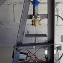
When I found the gearbox, it still had the armature and bearings attached. I cut off the end stub to keep the keyed shaft to drive the gearbox input via a 8mm flex coupler from a 3d printer.
Step 4: The Adapter Flange and Keyed Shaft


I left the outside diameter of the shaft as it was a perfect fit in the hub, but squared up the ends in the lathe. The 10mm flange plate was clamped to V blocks in the vise and welded to the shaft. The complete assembly was then faced in the lathe and assembled with the gearbox, but runout at the chuck face was a disappointing 0.18mm.
I then set the step index to continuous rotation and faced the hub and output flange face in the mill. This reduced runout to a much better 0.01mm.
Step 5: Checking Runout


Backlash measured at the lathe jaw was an expected 0.08mm, not critical as long as you keep going in the same direction.
There was radial runout , indicating the chuck wasn't centered on the flange, error crept in when marking and drilling the 4 mounting holes manually. Hopefully it will be taken care of by the use of the independent 4 jaw chuck.
Before cutting on the indexer, it needs to be set parallel to the mill table in both the Y and Z axis, this is done with a dial indicator on a printer rod set in the 4 jaw chuck.
Step 6: Some Uses


I used a scrap riser to mill a custom knob with 17 flutes as an example, because most traditional manual rotary tables and dividing heads struggle with dividing prime numbers.
Face engraving is another use, ie clock faces etc.
I redid the graduations on my lathe dials which were badly pitted from rust, erasing a lot of lines and numbers.
I guessed at 40 lines, because the compound slide had 20 marks on a 2mm pitch screw, it seemed logical the the cross slide would have 40 on a 2mm pitch screw.
Some of the originals didnt quite line up, so I'm guessing there were only 39 originally, using 40 as zero as well.
Still it is what it is, I'll stick with my 40 legible ones for the time being.
I needed two large holes in plates, 46mm and 40mm. I mounted the plates on the rotary table, set the indexer to continuous run and slowly lowered the cutting bit. This saved me from having to buy 2 different size hole saws that I might never use again.
I also used the center waste as a washer instead of the valve head that I previously used on the chuck adapter shaft.
The curved slot on the smaller plate was achieved using the degree function, 25 degrees switching directions at each end.
My Dremel juice wand from a previous Instructable would have benefited greatly from the use of an indexer.
Finally, cutting gears is another area where a dividing head is almost a necessity which I'm now able to tackle.

Participated in the
Reclaimed Materials Contest


