
Metal Shaper – A Homemade Machine Tool for DIY Metalworking Projects
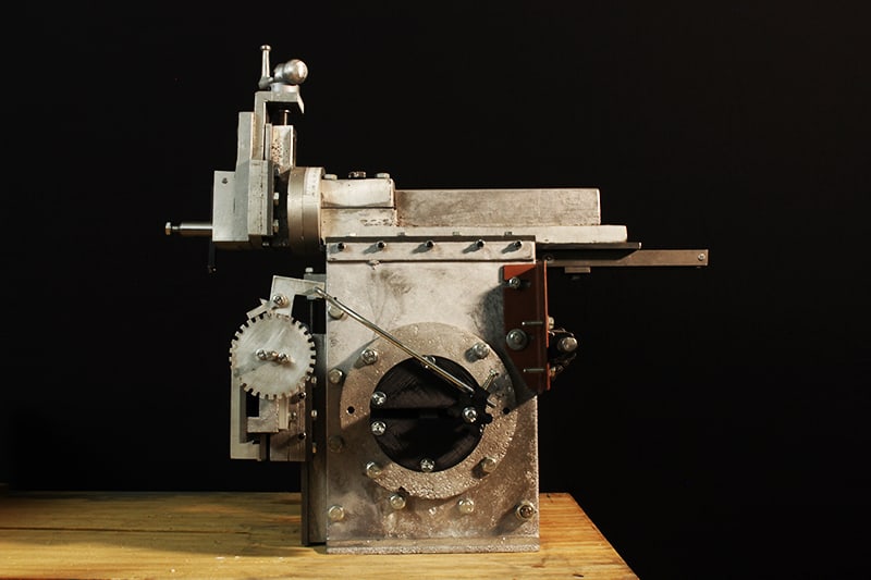
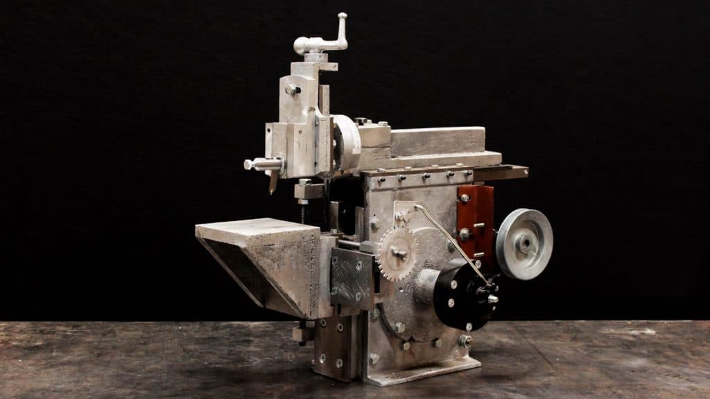
My homemade metal shaper is a tool for cutting metal from a work piece along a linear stroke. In addition to my home built metal lathe, I am using the shaper extensively as I build a horizontal milling machine.
I also edited more extensive footage and discussion of the build in individual videos. There is about 3.5 hours of video (excluding live stream of first cut) spread over 16 videos in this play list. Check the full playlist out for the entire scoop. Or jump right to the completion video below:
The Design
I built these machines referencing many design details presented in David Gingery’s 1980 book series, Build Your Own Metalworking Shop from Scrap. The metal shaper book is number four in the series. I have deviated from the stock design in a number of ways the largest of which are the use of lost foam casting, 3D printed parts, use of metric fastners, and use of available tools and materials (very different availability from the 80’s).
Below you’ll find my affiliate links. If you click the link and make a purchase, I receive a commission.
This build was inspired by the design of David Gingery. Where I improved on his design, I will note it below. If you decide to build this machine, you really should have a read through David’s book.
Supplies
Tools
Before you can build the shaper you definitely will need a selection of tools. All the tools I use in the machine shop and in making video can be found on the tools page. For convenience here are the most relevant tools to this project:
- Lathe – Homemade or off-the-shelf (https://amzn.to/2YgfzXV)
- Foundry – Homemade
- #6 Crucible – http://amzn.to/2lBBOEC
- Surface Plate – http://amzn.to/2lfqRHL
- Belt Sander – https://amzn.to/2TZZuWR
- File
- Viking 2.5-13mm Drill Bits – https://www.mcmaster.com/30155a57
- Drill Press
- Tap and Die Set
- Digital Calipers
- Micrometer
- Vise
- 1-2-3 Blocks –
- Locking Pliers
- C-clamps
Hardware, Bar Stock, Rod Stock
At the start of this project, I was determined to build this project using metric dimensions for hardware, materials…everything. I special ordered metric cold rolled steel 🙄. As the project progressed, my perspective on where metric hardware should be used changed.
I live in the US where rod and bar stock, hardware, and tooling generally is not stocked in metric sizes. Because all vehicles since ~80’s have used metric fastners and because cheap import tools and furniture are now prevalent, using metric fasteners is a very economical way to go. Special ordering metric rod and bar stock definitely is not.
Most of my dimensions are derived from David Gingery’s design and adapted for metric hardware and dimensions–however due to local hardware availability I used a mix 🤭.
Conclusion: I have standardized on metric fastners, meaning I need metric taps–which I can buy locally. I use standard rod and bar stock now. I use standard bronze bushings and shaft collars. I use standard threaded rod. I lay out parts in the dimensions called for in drawings. I design everything in metric and when laying out parts according to my own dimensions everything is cut to metric dimensions. I turn parts to standard dimensions since my micrometers measure in inches.
Casting Feed Stock
Most of the aluminum from this project came from transmission housings and an intake manifold. I broke this material down in a fire pit.
I also alloyed C932 bronze from scratch for the bearings in the scotch yoke. I ordered zinc, tin, and lead ingots to alloy. I used copper I salvage from electrical wiring.
Casting
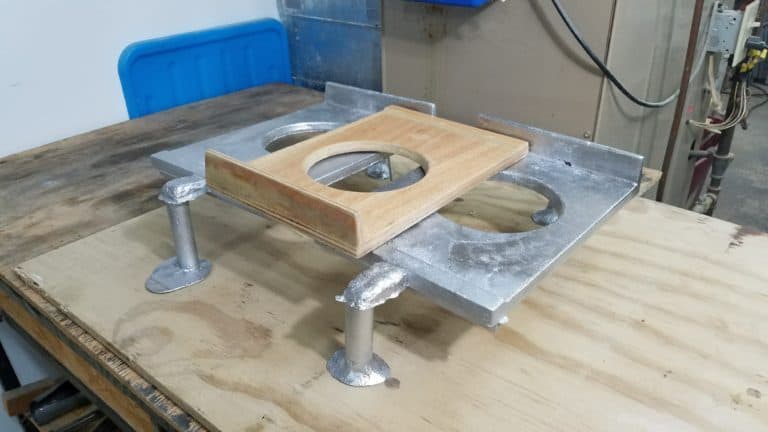
During this project, I moved from green sand to lost foam casting as my primary technique. This makes sense because I am casting only one or two of each part. I love the dimensional fidelity of the lost foam casting technique. I use plaster of Paris as a refractory coating mixed to a runny peanut butter consistency to coat the foam patterns. After the coating dries, I place the patterns in bone dry play sand. I do not include vents in the patterns based on information in Lost Foam Casting Made Simpleand because I haven’t had issues with mold filling.
The Result
The metal shaper has been far more valuable than I initially anticipated. Flatting stock on the 12″ disk sander, then sanding on a flat surface, then scraping was a very labor intensive way to get a flat part. Now I can stick a part on the shaper. It still takes 45 minutes to flatten, but I am no longer exhausted afterward. Plus I can work on something else while the shaper works on the part.
The shaper is SUPER useful, although once I build the mill it may not be as revolutionary.
Using the shaper
Like I mentioned earlier, I have really been excited to use the shaper on the mill project.
The shaper is pretty easy to use. Once the stroke length markings on the scotch yoke, it is pretty simple to match the stroke to the workpiece length and center it on the workpiece. I have a variable speed drive so dialing in the shaper to get reasonable surface finishes is a reasonable undertaking. I was really hooked after I machined the spindle head on the mill which was the first time I used the shaper on a project.
Things I would change
I will update this list as I use the shaper more and according to maintenance on any parts that wear prematurely.
Independent Drive Issue
I wanted to mount both the shaper and lathe on the same cart. This left little room for a separate drive train. Furthermore, I upgraded the lathe with a salvaged treadmill motor and controller that provided continuous speed control. I used an intermediate shaft–held between centers on the lathe–to drive the shaper. A basic household 4-way switch provides a simple polarity swap to the DC motor to change direction, an important feature since the machines are mounted back to back.
This is cool because I can use the variable speed of my lathe to adjust the speed of the shaper. This is critical to getting good cut performance from the shaper. However, during the mill project more than once I have wanted to use both machines. Having dedicated drives would make it very nice to use both machines. I will probably fix this at some point in the future.
Column Design Issue
The shaper really needs to be a monolithic casting. When scraping the ram slide ways bearing surfaces on the side column castings, I moved the column to a new location. This cause movement between the sides despite having all fasteners and spreaders tightened securely. The casting needs to be a single unit. Although this wouldn’t be possible easily with green sand, I believe it could be accomplished using lost foam, but I won’t attempt to redo this aspect of the project since everything else is so dependent upon it.
Link and Ram Clamp Issue
One of the nuts on the bolt coupling the drive link to the top bearing on the scotch yoke loosened. I had to use Loctite on it after the shaper was completed. Accessing that linkage and ram clamp in general is absolutely infuriating. I would have had to take yoke and adjustment out–decoupling the bull wheel and removing the countershaft–just to access the linkage bolts. Fortunately with a magnet and patience I got the nut back on the bolt. Perhaps drilling hols in the column sides to access the bolt that secures the linkage to the scotch yoke and the adjustment would be a simple improvement. Just note, it is a tight fit with lots of moving parts.
Clapper Block Pivot Pin Issue
When I reamed the hole for the clapper block pivot pin, I used a home made d-bit. I tested this to ensure that it had a good fit with the pin I would use, and it was a tight sliding fit. I failed however to account for the fit in a long hole, since my test was in a short 10mm hole. When reaming the full with of the clapper block and box, the reamer or chips tended to abrade the hole causing it to be a bit larger except within about 15mm of the exit end of the hole. This causes a bit of springiness or about 1 thousandth of play in the clapper block at rest. To clarify, if I push on the clapper at rest it has a just perceptible travel until it bottoms out at the back of the clapper box. I will probably ream the hole with a proper reamer and install a slightly larger hinge pin at some point.
I add vise grips to the tool post during operation if I want the best cut possible. This is issue probably the biggest reason that adding the vise grips to the tool post makes such a big difference on cut quality.
Fast Return Stroke Issue
This is more an issue with the book than the design.
I fail to see how a fast return stroke would have any effect on the production capacity of the machine, even though the ‘Hot Air’ salesmen had a lot to say about it.
-David Gingery in the book The Metal Shaper: https://amzn.to/2UZ2LTV
In my own use of the shaper, I have definitely appreciated the fast return stroke. I adjust shaper stroke length so that the tool moves only over the top of the workpiece. I adjust the motor speed and automatic advance to get a good cut quality. Especially as the stroke length gets longer the duration of the cut versus return strokes differs. Effectively the cut duty cycle is improved and increasingly so with long stroke lengths. There are other shaper drive designs where the cut and return strokes are symmetric–think about a piston in an internal combustion engine. They can only run at 50% duty cycle.
The shaper is a slow machine. Improving the duty cycle while keeping the tool cutting at a consistent linear distance per second shortens the overall time required for a machining operation.
Downfeed Issue
The downfeed is where most of the thinking and operator intervention occurs. I am not happy with the backlash on this part or the smoothness of the fit between the downfeed slide ways and the downfeed casting. I will need to address this
The Build
Column – The Machine’s Base
The column sides were the last part that I cast using green sand. I cast two of these parts. After that I switched to lost foam casting. The column front was the first part that I cast using this technique. I scraped the column front, installed the vertical slide ways, then assembled the column components including the rear spreaders. As I mention in the section on things I would change, I really wish that I had cast the column as a monolithic casting.
Ram, Bull Wheel, and Scotch Yoke – Driving the Ram
With the column complete, I moved on to the ram. I cast the ram and ram cap using lost foam. I used the lathe to face off the ram then attached it to the ram slide ways: the cold rolled steel at the bottom of the ram that rides on the column bearing surfaces.
I glued sand paper to the bottom and side of the ram ways and used it to sand the columns bearing surfaces followed by scraping. I installed the clamps, gib and adjustment screws.
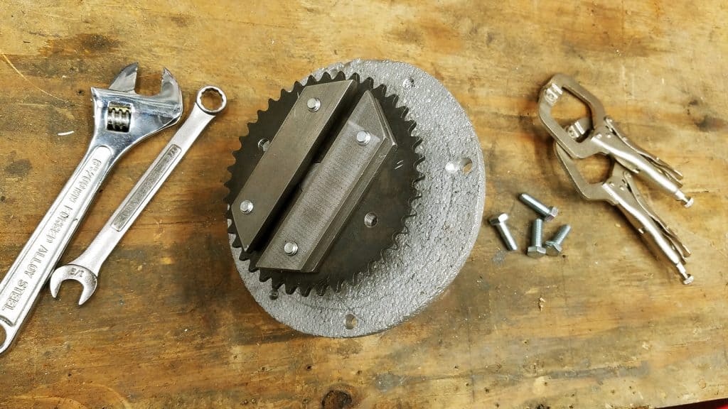
With the ram sliding smoothing in its clamps atop the column, I switched gears to the bull wheel. I cast and bored the crank bearing support to accept the bronze crank bearings. I used a 40 tooth gear from McMaster with several pieces of cold rolled steel as an adjustment slot. The crank pin is just a shoulder bolt.
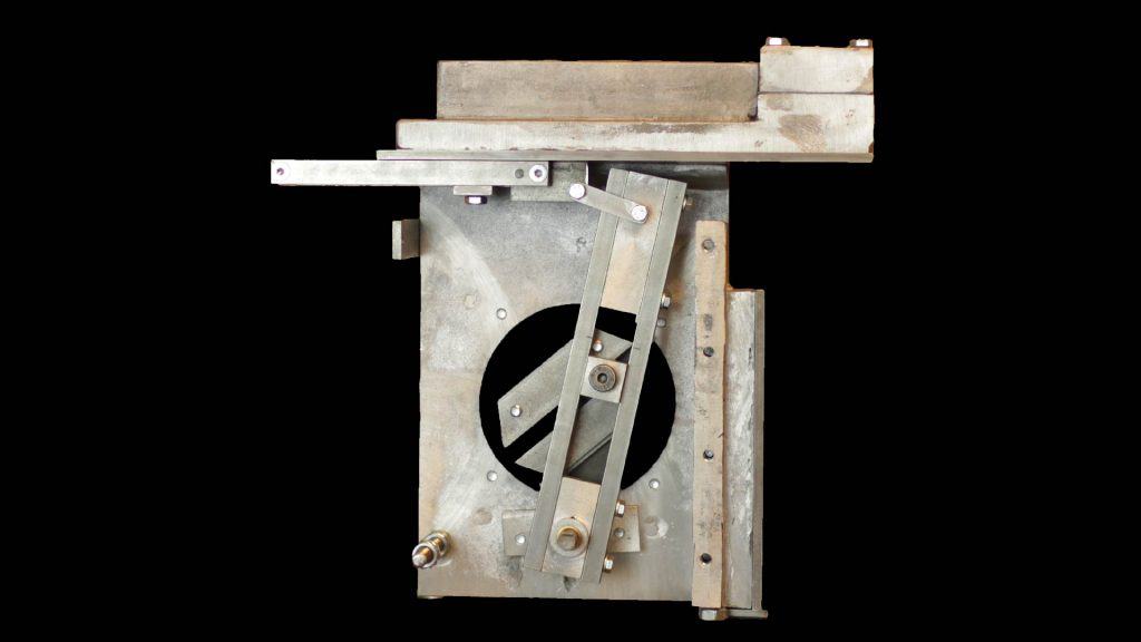
The scotch yoke is one of the neatest parts of the project. Two castings at the bottom hold a pivot rod. There is a cast at the top and bottom of the yoke, both with bronze bearings press fit into them. Note these are the bearings I alloyed from scratch. After assembling the yoke, I fit the slide block to the yoke. The slide block also has a bronze bearing pressed in where the crank pin can rotate driving the yoke back and forth.
The top yoke casting is connected to the drive link. The drive link is connected to the ram clamp. The ram clamp is connected to the head bone…no wait the ram clamp is connected to the ram. It facilitates adjustment of the stroke center point relative to the work piece. This area could use a bit of modification as I mention in the section on what I would do differently.
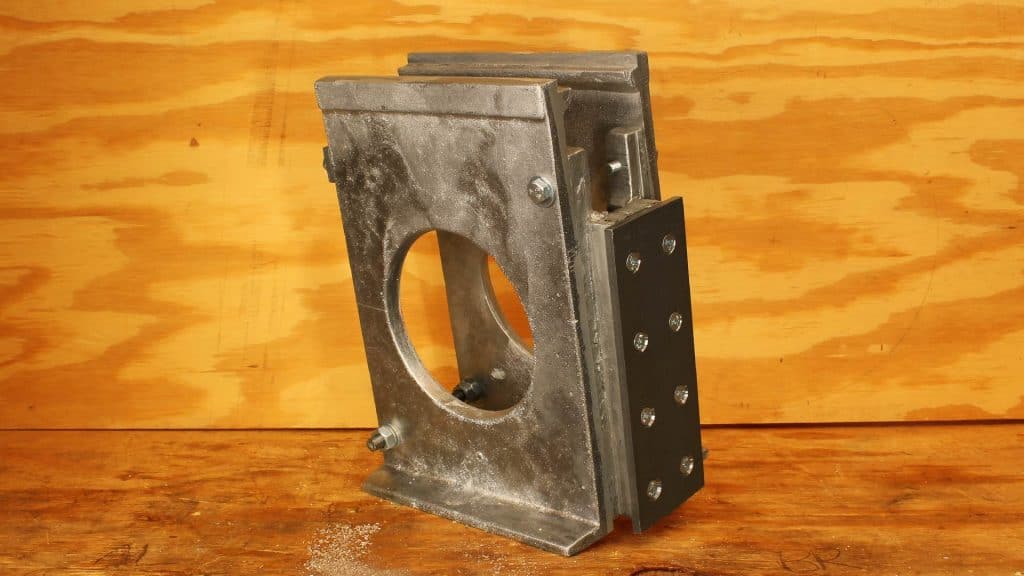
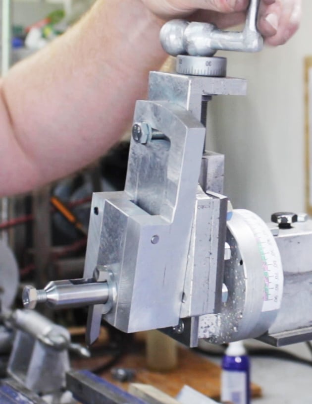
Rotating Head and Down Feed
I cast the protractor disk on a 20mm arbor. Afterward I drilled the arbor, then drove it out. I cast the rotating head onto a 20mm arbor with centers in each end. The centers gave me the ability to face off the rotating head in the lathe between centers as well as machining a recess for lock bolt on the arbor. I cut the arbor off at the front of the rotating head then scraped that surface for mounting the down feed ways.
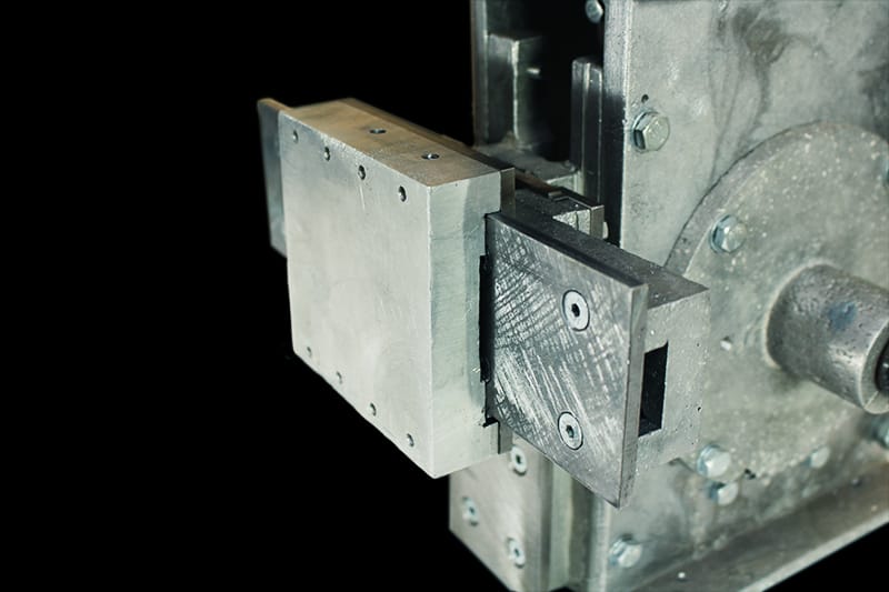
I cast the down feed slide and fit it to the down feed ways using the standard technique: sand, scrape, clamp, gib, adjustment screws. I sanded and scraped the front of the down feed slide. After casting the clapper box, I sanded and scraped its back so it would mate well with the front of the down feed slide.
I cast the clapper block. I sanded it then scraped it dead flat on the parallel sides. To get it to fit in the clapper block, I sanded the clapper box using a 1-2-3 block with sandpaper glued on. Then I used a gauge made of sheet metal to dial in the channel in the clapper box. I made some fine tuning for fitment of the clapper block into its box using a scraper. I drilled and then reamed the hole for the clapper block pivit pin fixing in place with a set screw.
I turned the tool holder, drilled and filed a square hole in the holder, tapped it for a bolt to hold the tool. Then I drilled bored and counterbored the clapper block for the tool holder.
Work Holding – Support, Slide, Work Table
At this point the most difficult aspects of the shaper build were behind me, I cast the cross slide support and cross slide using lost foam and fit using the normal technique: sand, scrape, clamp, gib, adjustment screws. Note: I am really proud of how nice the fit between the cross slide and the cross slide ways turned out…really smooth.
I fabricated and mounted the vertical and horizontal travel lead screws as described in the book with the exception of the horizontal feed crank. At the recommendation of Cadre Patron, Ben Wilhoite, I designed a crank with an integrated bearing and 3D printed the parts since it is a fairly low stress application. I am really happy with this design
Autofeed – 3D Printed Design Departure
For the autofeed mechanism, I again made a significant departure from the stock design. I kept the ratchet wheel and pawl design because I loved the traditional mechanical aspect of that design feature. It would be pretty straightforward to attach a stepper motor and replace its function with an electronic solution. Although I may do so in the future for now I am happy with the mechanical solution.
The feed crank instead of being fabricated of metal is now a fully 3D printed design that includes a ball bearing at the crank. There are two 3D printed nut handles that facilitate easily changing the step over.
Did I miss something?
Shoot me an email if I missed a detail not included in the book or addressed in a website article.